|
|
Stage Mechanism
This is an
adaptation of Bruce Berggren's Crushing Sleave Staging Mechanism
which can be found at http://www.geocities.com/wrgarage/stage.htm .
I have
adapted it so that it can be made with the materials
that I could find in the UK. There seems to be a lack
of materials that are suitable for the making of
water rockets in the UK so here is what I came up
with (after searching the shops and everywhere else
for over six months).
For
computer modelling purposes, it has a Stage
Mechanism Diameter of 15mm and a release
differential pressure (with one hose band) of
around 45 psi or roughly 3 Bar. The latter can be
increased by using extra or wider bands.
Materials
To make one of these, you will need:
- Two bottle tops - the type with a
thin, plastic sealer in them;
- around 1" of 21.5mm PVC Pipe
(just normal overflow pipe);
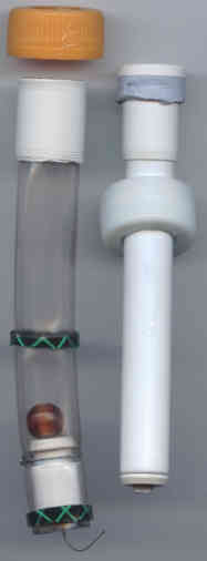
- around 5" of 15mm PVC Pipe (this
stuff is pretty neat (it is made from
three layers - picture on the right)
but it appears to be standard. It is
marked with the following -
"Speedfit 15mm B-PEX to BS7291 :
Part 3:1990 Class S 12 BAR 20ºC - 4
BAR 82ºC - 3 BAR 92ºC
9927/0609/279");
- around 4" of 20mm o/d
transparent, flexible PVC Hose
(garden irrigation type - it fits
snuggly inside the 21.5mm o/d PVC
tubing);
- around 1/2" reinforced Garden
Hose cut into two pieces around 4mm
wide;
- 22mm Tube Inserts (Speedfit J158 for
polybutylene pipe (see15mm pipe
above));
- 15mm Tube Inserts (Speedfit J157 for
polybutylene pipe (see15mm pipe
above));
- two Paper Clips;
- a Plastic Bead;
- some Blu Tack or similar - epoxy
resin may do this instead for the
bead - see construction details
below;
- some PET plastic from the side of a
bottle; and,
- some 4mm to 5mm i/d plastic pipe
(keep your eye open for this stuff -
lolly handles, child's balloon sticks
(a balloon on an adaptor on a hollow
stick - the type that they get given
as a store promotion when you are out
shopping and they quickly become a
liability as the balloon bursts and
the little dear wants another one:-).
|
|
Construction
 Nozzle Nozzle
- Make good the end of the 15mm pipe using a pipe
cutter. This pipe will cut okay but once you have
got through to the blue plastic (which is very
ductile and will stretch instead of cut) you have
probably weakened the inner part of white plastic
enough to finish the job off with a sharp knife.
Make sure that the end is flat but DO NOT get rid
of the burr on the inside of this end.
- Using the same cutting technique, cut the other
end giving you a tube around 11cm long. Remove
the burr at this end (the water will flow into
the pipe through here so it needs to be
reasonably smooth).
- Get one of the 22mm Tube Inserts and ram the
inlet end of the 15mm pipe into the end without a
flange (as per the picture on the right). Use a
small hammer but don't hit it too hard or the 22m
Tube Insert will split (it may not do this
straight away so if you have hit it too
hard, you may not know until it is too late). It
is tight enough when you can't pull it off the
tubing using a similar force to that of the
pressure in the rocket during the flight.
- Cut a hole in the centre of a bottle top so that
the Tube Insert just fits through if and then a
hole in the centre of the bottle top seal that is
just smaller than the Tube Insert. Put the seal
into the top and slide them onto the pipe.
- Get one of the 15mm Tube Inserts and roll up a
strip of bottle side PET (around 20mm wide x 20cm
long). Pull the PET strip over a sharp edge to
make it curl and then roll it up so that the hole
in the middle is as small as you can make it.
Trim the PET strip so that it will roll up small
enough to get into the flange end of the 15mm
Tube Insert (you may have to trim it so that the
external diameter is small enough to do this) and
then tap it home with a small hammer.
- Cut approximately 25mm of the 4.5mm i/d tubing,
making sure that the ends have no burrs. You may
find that this will fit snuggly into the hole in
the rolled PET but I found that there was enough
room to insert another layer of PET. Roll the PET
up (you want enough to go around the outside of
the 4.5mm i/d tubing - the PET that is already
there is a spiral so get the outer end of the new
piece to butt upto the inner end of the outer
piece thus forming a tight continuation of the
spiral. I found that one layer was enough), put
the 4.5mm i/d tubing in it and carefully tap that
into place.
- Using a sharp knife, cut a smooth, tapered inlet
to the 15mm Tube Insert nozzle that you have just
made. The water has to flow into the nozzle
throught this so it should be smooth and conical
(get that k nozzle factor as low as
possible).
- Push the tube insert nozzle into the end of the
15mm tubing - this should be a tight fit and the
burr should make it more so. Be careful not to
damage the end of the 4.5mm i/d tubing. Using a
sharp knife, take off any burrs that have formed
- a burr on one side will push eht jet over to
one side and make your rocket loop in the air
instead of flying straight.
- Take some Blu Tack and role it into a small
cylinder (around 6mm diameter) and cut off around
5cm of this. Roll around the 22mm Tube Insert
below the flange, forming it into a seal, so that
it is slightly narrower than the internal
diameter of the bottle neck.
- To fit into the bottle, push the flange with the
Blu Tack seal into the neck of the bottle so that
the seal is below the end of the nozzle. Screw on
the bottle top and then pull then pull the nozzle
so that the flange slides towards the top,
squashing the seal and making it it seal. The
flange and the hole in the bottle top will keep
the nozzle aligned - this is why it is important
to get the hole central. This is effectively a
removable, watertight seal.
Crushing sleeve
- Get the cut-off end of a pop bottle (the nozzle
and a few inches of neck) and push through, from
the neck end, some 21.5mm o/d plastic overflow
pipe so that around 5cm protrudes through the
nozzle end.
- Heat up the very end (around 1cm) using a cooker
or a candle - the surface will change its texture
- and pull the tubing back into the bottle so
that only around 4mm protrudes. Push the end down
onto a flat surface, being careful to make sure
that the end is square. The aim of this is to
flare the end of the tubing so that it is
slightly larger than the end of the bottle neck -
the bottle neck that you are using will help to
keep the PVC tubing in shape. Don't press too
hard as you may flare the end unevenly. Once you
have done this, it should have around 1mm of PVC
pipe that should not go through the bottle neck
(that doesn't mean that you have squashed all 4mm
into just 1 mm though - it tends to slide as you
are pushing it).
- Cut the pipe using the pipe cutter around 25mm
from the flared end. Do not remove the burr -
this will help to grip the flexible PVC tubing
when the system is not pressurised. You should
now have a short length of pipe that will not go
completely into a bottle and should be fairly
easy to remove from a bottle neck.
- Cut around 15cm of 20mm o/d clear flexible PVC
tubing making sure that both ends are flat and
square. Push one end into the length of 21.5mm
o/d pipe that you have just made so that the end
of the flexible PVC pipe is flush with the flared
end of the 21.5mm o/d pipe. The burr on the outer
pipe should help to hold the flexible pipe in
place.
- Cut a piece of 15mm o/d pipe around 15mm long,
leaving the burrs. Push a 15mm Tube Insert into
the pipe leaving around 5mm gap between the
flange and the end of the pipe (see bottom of
diagram below).
- Get a paper clip and straighten it out. Bend
around 6mm of the end back on itself, using a
pair of pliers, so that it is a tight fit in the
hole in the plastic bead. Push the straight end
of the paper clip through the hole in the bead
and pull the bent over end into the hole so that
it is a tight fit.
- Push some Blu-tack into hole to seal it (it is
only going to have any serious pressure along it
for a fraction of a second) or, as an
alternative, fill the hole with epoxy resin,
using a flatened piece of Blu-tack as an end to
the mould formed by the inside of the bead (when
the epoxy is set, remove the Blu-tack).
- Put the paper clip in the bead through the 15mm
Tube Insert and bend the end over so that it
won't come out. remember to leave a few
millimetres of travel so that it can act as a
valve.
- Push the 15mm Tube Insert into the end of the
20mm o/d clear flexible PVC tubing so that the
ends are flush.
- Cut two rings of garden hose and fit them in the
positions shown on the diagram. To get them over
the PVC tubing, you will need to stretch them
first. I did this by putting the handles of two
table knives into the hose rings and twisting
them to stretch the rings. After a few minutes
the rings shrink to their original size. I found
it necessary to put a ring at position 2
(not seen in the original US design) because the
flexible tubing I could find in the UK was not a
close enough fit - without some initial seal such
as that provided by this extra ring, too much air
escaped during pressurisation. This works like a
dream.
- Straighten out the other paper clip and wrap it
once around the 20mm o/d plastic tubing, twisting
the two ends together using pliers. Cut off the
excess and bend the twist down so that it is flat
to te side of the tubing (remember that this
assembly has to pass through the neck of a
bottle).
- Cut a hole in the centre of a bottle top so that
the 15mm o/d PVC pipe fits through and then a
hole in the centre of the bottle top seal of the
same size. Put the seal into the top. Be careful
to make sure that the 15mm PVC pipe will fit
smoothly by making sure that the hole is central.
One way of doing this is to put the flexible
sustainer end into the end of a bottle and to
make the hole in the bottle top (being careful
not to cut the flexible PVC) in situ - passing
the 15mm PVC through the hole close to finishing
to make sure that it is aligned properly. A
tollerance of 0.5mm is okay here as the seal is
made by the end of the PVC pushing against the
bottle top seal.
- To fit into the bottle, wet the garden hose rings
(they are a tight fit) and push the assembly into
the bottle as shown in the diagram. The 21.5mm
PVC pipe should stop short of going all of the
way in. Screw the top down and the 21.5mm o/d PVC
pipe and the 20mm o/d flexible PVC tubing should
fit flush to the seal. The pressure in the bottle
will push these harder against the seal for an
air tight seal in use.
 Operation Operation
Filling
- With the booster end of the Stage Mechanism
in place on the top of the booster, fill the
booster to the appropriate level and mount on
the launcher. Beware of the tendancy for the
booster to empty if the one-way valve is not
in place (this shouldn't happen but it is as
well to be aware of this in case it does).
An alternative method is to put a normal
bottle top on the top of the booster, fill
the booster with the appropraite amount of
water, place it in position on the launcher
and, when it is water tight, take the top off
and replace it with the crushing sleeve
mechanism.
- Fill the sustainer (second stage) to the
appropriate level.
- Push the sustainer nozzle in, along with its
Blu Tack seal, screw on the top and pull the
nozzle up so that the seal fill in the space.
If the hole in the top is central, the nozzle
will be straight.
- Put the sustainer onto the booster. The one
way valve (the bead) will stop the water form
flowing into the top of the booster.
Pressurisation
- Before pressurisation, water flow into the
booster from the sustainer is stopped by the
one way valve and the sustainer is held in
place by its weight.
- When pressurisation commences, the pressure
at a
increases, forcing air past the one-way valve
into b.
Air does not pass to atmosphere at 2
because of the light pressure seal caused by
the garden hose. Note that the pressure from
the garden hose is never enough to hold the
15mm pipe in place.
- As the pressure increases, the pressure in a,
forces the flexible tubing at 1
onto the surface of the 15mm PVC tubing
(displacing the air that was in this space to
atmosphere - c)
which provides a sufficient grip to stop the
PVC tubing from being released. This force
also pushes the tubing against the Cap Seal
and enhances its seal. The more the pressure,
the more the gripping force, the more the
seal.
- Once pressurisation has been completed, the
pressures in a
and b
are equal. The one-way valve only has the
hydrostatic pressure of the water in the
sustainer on it as it did before
pressurisation commenced and the pressure
from the paper clip at 3 is sufficient to
hold it in place.
Release
- When the rocket is released, the water is
ejected from the booster and the pressure in
the booster decreases. The whole rocket is
accelerated to maximum velocity. The one-way
valve holds the water and the pressure in the
second stage of the rocket and the pressure
on the flexible tubing holds the second stage
nozzle pipe in place.
- Once the water has finished, the air escapes
from the booster and the pressure carries on
falling towards atmospheric pressure. The
restraining pressure on the flexible tubing
diminishes until the pressure at the end of
the second stage nozzle (between 2
and 3)
- still at the initial pressurisation
pressure - is suffucient to overcome both the
reduced grip on the nozzle and the lower
acceleration from the booster.
- At this point, the nozzle, lubricated by a
small amount of water from the sustainer, is
forced out of the flexible tubing and the
second stage is released - still at the
initial pressurisation pressure.
During the depressurisation of the booster, two
things happen:
- The force holding the sustainer in place
reduces as the acceleration falls - trying to
force a release when the force that is a
result of the pressure on the area of the end
of the nozzle (15mm diameter in this case)
exceeds the force from accelerating the mass
of the sustainer with its water; and,
- The pressure in the booster falls by the
amount required to release the grip on the
side of the nozzle.
Note that this pressure is the difference between
the pressure in the booster and sustainer and is not
relative to the pressure between the inside of the
booster and the outside air. This is because the
pressure on the inside of the tubing is derived from
the sustainer via the end of the sustainer nozzle
because the one-way valve (the bead) prevents the
water from flowing into the booster.
As a result of this, it is possible to measure the
release pressure by putting the sustainer nozzle onto
a spare bottle (a 1 litre will do) with a little
water in it (not to weight too much) and putting the
booster release mechanism onto a bottle that can be
pressurised (two bottles bottom to bottom like the 4
litre rocket or one with a tyre adapter in the base)
and pressurising the base bottle in 5 psi steps,
releasing the pressure each time to see if the
release mechanism releases. I found that it did this
for this mechanism at 45 psi. It is not unreasonable
to assume that it will release, dropping from, say,
100 psi, when it gets to 55 psi if the acceleration
makes the force on the nozzle from the sustainer fall
below the force from the end of the nozzle (100 psi x
0.27 square inches = 27 lbs force or 122 Newtons).
The numbers that you put into the computer model for
2 stage optimisation are 45 psi and 15mm.
 Back to
the 2 Stage Rocket Back to
the 2 Stage Rocket
Back to the Water Rocket Index
|
|