These are two staging mechanisms that are in
general use. The diagrams show the release
mechanisms - there should be extra support
for the upper section (in the form of a
straight side bottle section to rest on) or
the mechanism will be damaged under the
acceleration of launch.
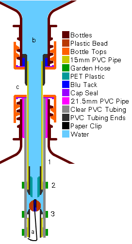 Crushing
Sleeve
 The
sustainer and the booster are linked
according to the diagram. The pressures in
the top (b) and bottom (a) bottles are the
same as the bottles are pressurised from the
bottom. The one way valve prevents water from
returning to the bottom
  bottle.
On pressurisation, the flexible PVC tubing
grips the PVC pipe (1), stopping it from
escaping. When the rocket is launched, the
pressure in the booster (a) falls and
eventually, the PVC tubing (1) is released.
If the weight of the top bottle under the
acceleration from the booster is greater than
the force from the pressure in the top bottle
acting on the end of the nozzle (the outside
diameter - 15mm in this case) then the
sustainer will not be released. If the
pressure is sufficient then it will break
free.
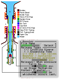
Select
Crushing Sleeve. The release
pressure is put into the top text box and the
diameter of the outside of the sustainer's
nozzle section is put into the bottom box
To find out the release pressure, assemble
the two bottles (with a little water in the
top one to act as a seal) and take the
pressure up, 5 psi at a time, releasing the
pressure in the bottom section until the top
bottle breaks free. I found that for the
version on the right, 45 psi was needed. The
diameter is 15mm in this case (the o/d of the
15mm pipe).
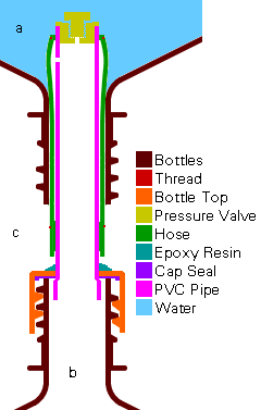 Expanding
Tubing - Single Valve
 The booster
has a special top with an expanding rubber
sleeve that swells under pressure, holding
the sustainer in place. There is a non-return
valve on the top of this that allows air to
pass from the booster (b) to the sustainer
(a) once there is a pressure difference
between them. This has the effect of allowing
a sufficient pressure differential to build
up in order to inflate the tubing and, allows
compressed air to travel into the upper
  chamber.
On launching, the pressure in the booster
(b) falls and the tubing collapses, releasing
the sustainer (a). Again, if the pressure in
the sustainer is sufficient to force the two
sections apart, it will, or it will wait
until the acceleration has fallen enough for
this to take place.
Select
Expanding Tube and One
Valve. Put the pressure at which the
valve starts passing air in the upper box and
the diameter of the inside of the neck in the
bottom box.
Note that with this arrangement, the
pressure in the sustainer is lower than that
in the booster by the differential pressure
(around 20 psi or so) and the diameter is the
nozzle internal diameter (a bottle neck -
21mm or so).
There is nothing to stop you from putting
a t-nozzle on top of the release mechanism to
give you a smaller nozzle diameter. It will
still have a high release mechanism diameter
but the nozzle will be more effective. To
find out the diameter of the t-nozzle
required, elect to optimise the diameter and
the value for Nozzle Diameter will be the
t-nozzle diameter.
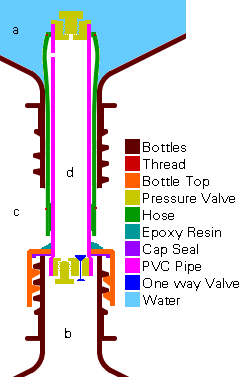 Expanding
Tubing - Double Valve
 Again, the
booster has a special top with an expanding
rubber sleeve that swells under pressure,
holding the sustainer in place. There is a
non-return valve on the top of this that
allows air to pass from the booster to the
sustainer once there is a sufficient pressure
difference between them. This has the effect
of allowing enough of a pressure differential
to build up to inflate the tubing and, allows
compressed air to travel into the
 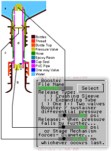 sustainer
(a).
Before air can get to the upper valve, it
passes through the one way valve at the
bottom. This just lets air in so that during
pressurisation, the pressure in the release
mechanism is the same as in the booster.
On launching, the pressure in the booster
falls. Once the pressure difference between
the booster (b) and the inside of the release
mechanism (d) is great enough, air passes
from the release mechanism (d) into the
booster (b). Once the pressure in the release
mechanism (d) has fallen further by the
pressure difference required to inflate the
expanding tubing, the sustainer is released.
Again, if the pressure in the sustainer (a)
is sufficient to force the two sections
apart, it will, or it will wait until the
acceleration has fallen enough for this to
take place.
Select
Expanding Tube and Two
Valves. Put the pressure at which
the top valve starts passing air in the upper
box (20 psi in the example), the pressure at
which the bottom valve starts passing in the
middle box (50 psi in the example) and the
diameter of the inside of the neck in the
bottom box.
Note that with this arrangement, the
pressure in the sustainer is lower than that
in the booster by the differential pressure
(around 20 psi or so), the sustainer is
released once the pressure in the booster
has fallen by the sum of the differential
pressures of both valves, and the diameter is
the nozzle internal diameter (a bottle neck -
21mm or so).
Again, there is nothing to stop you from
putting a t-nozzle on top of the release
mechanism to give you a smaller nozzle
diameter. It will still have a high release
mechanism diameter but the nozzle will be
more effective. It is calculated in the same
way as in the single valve description above.
Return to 2
Stage Optimisation
Copyright
©2000 Paul Grosse. All Rights Reserved