Click Here to go to the MkII aerial video camera Basics on how to make an Aerial Camera.
Discussion
One problem is talcum powder from the parachute getting into the lens so I decided to have a separate chamber for the camera. The cover is pulled off by the parachute at apogee and when the cover is clear, a short cord pulls a piece of plastic away from the button that then presses the shutter release without jerking the rocket to much. Hopefully, the camera is pointing in the right direction at this time. Materials and equipment
Construction
Next, cut the top and bottom off a 2 litre bottle so
that you have a sheet of plastic from the sides (you
will need the top section later as well so don't discard
that). Put the camera into the cut-off 330ml bottle
and measure the space at the back so that you can make a
spring from the bottle-side plastic. Now, put the camera in position Next, make a plastic leaf spring by cutting a rectangle of plastic bottle wall with a width a little bigger than the slot you have just made and a length roughly the same as the length of the straight side of the 330ml bottle (see photograph lower-right and diagram lower-left). Using the soldering iron, narrow the leaf where it will go between the two sides of the slot and also make a notch in the top. Then, cut a slot in the leaf big enough to get a paper fastener through - the brass bulge in this will press the shutter release button. Push the paper fastener through and bend out the legs thus holding it in place. Next, cut off the threaded portion of the bottle
top-section that you cut off from the 2 litre bottle -
cutting right down to the flange (make sure that the
flange is not damaged in the process). Cut a section
of the threaded portion approximately 2cm long (measured
around the circumference) then cut the outer surface
of this (the side of it with the thread) half
way, approximately half way through with the soldering
iron. Soften the remaining part so that the two halves
fold over.
Then, get a small elastic band and wrap it three or four times around the end of a pair of scissors (or long-nosed pliers), open out the scissors and slide the elastic band in place so that it holds the paper fastener legs and the plastic piece that you have just made, together. This should hold the push rod in place on the legs of the paper fastener.
Then, cut another piece of plastic narrow enough to fit into the slot but long enough to cover it at both ends and an extra 4 to 5 mm (clearer in the photograph above right). Make sure that it can slide out without catching on anything as if it does, this may jerk the camera and lead to a blurred photograh. Make a hole in the end with the soldering iron - this will have a cord go through it to act as the shutter release with the cord pulling the plastic out of the way and the paper fastener pushing the shutter release button. Then, put a strong elastic band around the body of the camera holder so that it goes through the slot that you made in the top of the shutter release rod. Finally, cut a few supports in the camera holder body around this elastic band so that it will not slip out of place during launch (one of these can be seen clearly in the photograph above-right) and then you are ready to weld the camera holder onto the base unit. Next, cut off the threaded portion of the 330ml bottle
down to the flange in the same way that you did with the
2 litre bottle. You should now have two flat faces that
you can weld together. Place them in contact and using
the soldering iron, heat up the flanges and fold them one
over the other, mixing up the plastic as you go. This
will join the two but just to make sure, repeat as best
you can on the inside of the weld. Finally, allow to cool
down.
Using the soldering iron, make two holes in the tip of the supporting unit. Cut a ½ metre length of cord.(sealing the ends in the flame and cooling them in the water) and attach one end of it to the shutter release plastic piece, tying it firmly, attaching the other end to one of the holes in the tip of the support unit making sure that you attach it from the inside (see diagram at very top of this page). Cut a 1 metre length of cord (again, sealing the ends in the flame and cooling them in the water), put one end through the hole in the base unit and the other end through the tip of the support unit (again attaching it from the inside) - this holds the rocket up with the parachute. Having done that, a nose separates at apogee base unit can be fixed (see photographs above-right for base unit and left for nose cone and chute) in place and a parachute and nose cone fitted as usual. You now have two, nose separates at apogee events to worry about. During a normal flight, the rocket reaches apogee and, in the absence of differential air pressure and G forces, the parts start to separate. The drogue pulls the nose cone off the parachute which is then able to apply enough force (it isn't very much force at all as the drogue on its own will do this should the main chute fail to deploy) to pull the shorter shutter release cord out and trigger the taking of a picture. Then the longer cord becomes tight and the rocket is lowered to the ground under the main chute (as long as you remembered to take off all of the tapes that you used). To the pictures of the camera . . . To the pictures taken with the camera . . . Click Here to go to the MkII aerial video camera Another site relating to aerial
photography from rockets (although this one is pyro
rockets) is |
|||||
|
 The most impressive
photographs will obviously come from the highest part of
the flight and, as there is a pretty good incentive for
the camera to come to Earth as slowly as possible (the
camera that I use here can withstand the impact from a
fall of 150 feet onto soft grass), it only makes
good sense to use the deployment of the parachute the
trigger for the shutter. Using a low-cost camera is also
a good starting point as if the worst does happen, then
there will be little lost financially. Fortunately, there
are appearing on the market a number of cheap, single use
cameras that are very lightweight and small enough to
mount inside the body of a water rocket - the film is
exposed and the whole camera taken to the developers. For
my experiments into this field, I used a Kodak Fun Gold
Classic with '12 shots free'. Wow!!! It was only UK£1.30
(~US$2.00) more than the price of a roll of film and I
wasn't going to put my own camera into orbit.
The most impressive
photographs will obviously come from the highest part of
the flight and, as there is a pretty good incentive for
the camera to come to Earth as slowly as possible (the
camera that I use here can withstand the impact from a
fall of 150 feet onto soft grass), it only makes
good sense to use the deployment of the parachute the
trigger for the shutter. Using a low-cost camera is also
a good starting point as if the worst does happen, then
there will be little lost financially. Fortunately, there
are appearing on the market a number of cheap, single use
cameras that are very lightweight and small enough to
mount inside the body of a water rocket - the film is
exposed and the whole camera taken to the developers. For
my experiments into this field, I used a Kodak Fun Gold
Classic with '12 shots free'. Wow!!! It was only UK£1.30
(~US$2.00) more than the price of a roll of film and I
wasn't going to put my own camera into orbit. 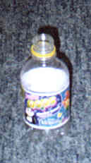 Pick a short, squat 330ml bottle and remove
the label and glue by tearing off the paper, filling it
with hot water (from the tap, not a kettle),
scraping off the excess glue then wiping off the rest
with IsoPropyl Alcohol (IPA). Cut off the bottom of the
bottle with the scissors where the bottle starts to
curve, leaving straight sides and a neat edge. Put the
camera in the bottle and crease the bottle so that two
creases are the same distance apart as the height of the
camera. Make a further two creases in the bottle the same
distance apart so as to make a rectangular cross-section
with the correct height but oversized base for the
camera.
Pick a short, squat 330ml bottle and remove
the label and glue by tearing off the paper, filling it
with hot water (from the tap, not a kettle),
scraping off the excess glue then wiping off the rest
with IsoPropyl Alcohol (IPA). Cut off the bottom of the
bottle with the scissors where the bottle starts to
curve, leaving straight sides and a neat edge. Put the
camera in the bottle and crease the bottle so that two
creases are the same distance apart as the height of the
camera. Make a further two creases in the bottle the same
distance apart so as to make a rectangular cross-section
with the correct height but oversized base for the
camera. Cut the plastic to the desired
width (so that the strip of plastic will fit flush
with the top into the gap at the back of the camera)
and then fold it in the same way as shown in the diagram
(the magenta coloured zig-zag). Just touch the
soldering iron on each side of the spring and the back to
make one mark on the left of both and two on the right (it
doesn't matter which way around you do this but doing it
will help you sort out the correct way around in the
field if you drop the spring for some reason).
Cut the plastic to the desired
width (so that the strip of plastic will fit flush
with the top into the gap at the back of the camera)
and then fold it in the same way as shown in the diagram
(the magenta coloured zig-zag). Just touch the
soldering iron on each side of the spring and the back to
make one mark on the left of both and two on the right (it
doesn't matter which way around you do this but doing it
will help you sort out the correct way around in the
field if you drop the spring for some reason).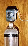 and push the plastic spring into
place.
and push the plastic spring into
place.  With a felt tip pen,
mark the position of the lens and the position of the
shutter release button. Make sure that you allow plenty
of room around the lens so that the plastic camera holder
does not get in the picture. Cut a largish hole for the
lens and then, for the shutter release, cut an 'I' shaped
hole as in the diagram, using the soldering iron. Turn up
the sides (using the soldering iron to form the
corner of the fold - just quickly run the tip of the iron
over the surface to soften the plastic (not to melt it)
and push the tabs into position) so that they are
perpendicular and form a sort of slot with the shutter
release button at the bottom.
With a felt tip pen,
mark the position of the lens and the position of the
shutter release button. Make sure that you allow plenty
of room around the lens so that the plastic camera holder
does not get in the picture. Cut a largish hole for the
lens and then, for the shutter release, cut an 'I' shaped
hole as in the diagram, using the soldering iron. Turn up
the sides (using the soldering iron to form the
corner of the fold - just quickly run the tip of the iron
over the surface to soften the plastic (not to melt it)
and push the tabs into position) so that they are
perpendicular and form a sort of slot with the shutter
release button at the bottom.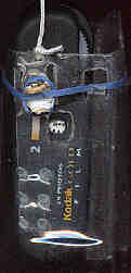 Weld the
two halves together to form a near solid lump - this will
make a rod to push the shutter release button in.
Weld the
two halves together to form a near solid lump - this will
make a rod to push the shutter release button in.  Cut a deep groove in
the top of this (approximately 3mm deep) so that
an elastic band can fit in it comfortably (Diagram on
left - front projection - shows groove and elastic band -
blue - that holds it onto the paper fastener. Photograph
on right shows, in addition, trigger elastic band -
horizontal blue band - in place). Soften the bottom
part of this piece and press it into the paper fastener,
folding the legs up along its sides.
Cut a deep groove in
the top of this (approximately 3mm deep) so that
an elastic band can fit in it comfortably (Diagram on
left - front projection - shows groove and elastic band -
blue - that holds it onto the paper fastener. Photograph
on right shows, in addition, trigger elastic band -
horizontal blue band - in place). Soften the bottom
part of this piece and press it into the paper fastener,
folding the legs up along its sides. 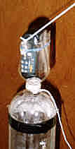 Next, spot-weld the
leaf spring in place by touching the other end of the
leaf with the soldering iron, long enough to melt the
surface of the plastic bottle underneath (if you are
not too sure about doing this, practice on some spare
sheet until you are confident). Position the welds
so that there is a body of spring running up the middle
that has not been welded (see photographs right and
above-right).
Next, spot-weld the
leaf spring in place by touching the other end of the
leaf with the soldering iron, long enough to melt the
surface of the plastic bottle underneath (if you are
not too sure about doing this, practice on some spare
sheet until you are confident). Position the welds
so that there is a body of spring running up the middle
that has not been welded (see photographs right and
above-right). 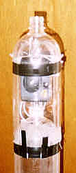 Then, make a hole in
the bottom part that a cord can pass through (as in
the photograph above). Having done that, make slots
in the base unit in the same way as is shown in the nose
separates at apogee page so that a supporting section can
fit in place.
Then, make a hole in
the bottom part that a cord can pass through (as in
the photograph above). Having done that, make slots
in the base unit in the same way as is shown in the nose
separates at apogee page so that a supporting section can
fit in place.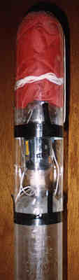 Once you have done
this, you can make the supporting section simply by
cutting the bottom off a 2 litre bottle so that the
camera fits nicely inside.
Once you have done
this, you can make the supporting section simply by
cutting the bottom off a 2 litre bottle so that the
camera fits nicely inside.