Having experimented with the extra thrust from using an open neck as the nozzle, I decided to have a go at making a rocket that flies reasonably well after the thrust phase of the flight. It had to have an aerodynamic nose and body, fins, be stable in the air and carry an optimised amount of water for the pressure range that I was going to use. Nose To modify the bottom of a pop bottle, you first of all need to have the connector described on the connector page. Attach this to the bottle (as described on that page) and pump up a fair pressure - between 1 and 3 BarG. Unscrew the pump, leaving the hose (with its one-way
valve) in place and start to rotate the At this amount of pressure, there is little danger of a catastrophic failure of the bottle during this process as the place where it is most likely to fail is where it is hottest and thinest. When it does fail like this, it is with a Pfffff and not a bang. (you can always use the straight sides for fins - see lower down this page). Body Modifying the shape of the body is similar in many respects to the process of making the nose into a hemispherical shape. This time, however, the idea is a controlled collapse of the body, down to the required conical shape.
Make sure that you keep the nozzle aligned with the axis of the bottle - if you do not, it may always fly in an arc. Do not heat too much near the connector part of the bottle as this may start to blow out making it impossible to fit properly on a launcher. If you have problems with bottles fitting launchers and cannot get hold of the correct internal or external 'o' rings, you can expand or colapse slightly the upper or lower part of the nozzle accordingly so as to get a good fit. Again, once you have got it just the way you want it (b), put it in cold water to make it set. Practice makes perfect and it may take a few attempts to get it just right. Fins
Ideally the fins should be as far back as possible (without getting in the way of the launcher) and present as little drag to the rocket as possible when flying straight. they can be virtually any shape as long as the do the job of providing a sideway area at the rear of the rocket (see the next section on stability). I have found the best material for fins to be the same plastic that the bottles are made from. There is enough of this material in two 2 litre bottles to make the 3 or 4 fins that you require. Cut out the part of the bottle with the straight sides (1) and cut along one side (the bit with the glue on it is the best place to cut as this is unsightly)(2).
Flatten this bit out and fold back on itself so as to cancel out the tendency to curl (3). Make a template of the fin shape that you want (sized so that you will get two out of each bottle with a minimum of waste) and cut them out (4). You can either glue the two sides of each fin together, or you can tape them around the edge - the latter making it easier to see the fins when in the air. Fixing the fins Two methods:
Ideally, you want the thing to fly straight as any deviation from this will reduce the rocket's performance. Once the thrust phase of the flight is out of the way, the rocket is essentially in free fall (even though the first part of this free fall is upwards). For it to maintain its attitude in the air, there are a few things that you will need to consider: the positions of the effective centre of drag (COD) and the centre of gravity (COG). With a small rocket such as a water rocket, it is fairly easy to find out where they are but you also need to know what to do with them. First, how to find them. To find the COG, try to balance the rocket on its side so that you find a point that is reasonably stable. The COG is above this, on the axis of the rocket as in the diagram. (If it is not on the axis, you have a problem). To find the COD, cut out a piece of cardboard the same shape as your rocket as viewed from the side and find its centre of gravity (it need not be the same size as the real rocket as long as it is to scale and that you remember to scale it back when you have found it). The centre of gravity of the cardboard model corresponds to the centre of drag. Once you have put your fins on (which you should have done before you started trying to find the COD), the COD is going to remain almost in the same position, no matter what you are going to do with the rocket (within reason) wheras the COG may be moved by adding weight to the rocket. Ideally, the rocket should weigh as little as possible so you want to add only the barest minimum of extra weight.
To move the COG forwards, make a mark with a pen on the rocket where the COG needs to be and then tape coins to the front of the rocket (at point w). Once you have found out how many you need, you can make a neat job of it with tape (or glue) so that the aerodynamic qualities that you have devoted so much of your time to are not lost. I found that for the 2 litre bottle that I did this to, I needed 8 x 2p pieces - for the 1 litre and 250 ml, I needed 6 x 2p pieces. (A UK 2 pence piece weighs approximately 7 grammes or ¼ ounce). See Bottle Modifications for Better Flights for an explanation of air and water flow. Water We now have a water rocket that is aerodynamically sound. We know that we will be able to pump it up to a pressure of between 4 and 6 BarG (between 60 and 90 psig) and we can measure it. So, how do we know how much water to put in it? We need to know its tare weight, capacity, diameter and nozzle dimensions to be able to work out how much water it will need for a flight with the greatest height. We can measure its nozzle, body diameter and weight it empty to get its tare weight but we have changed its capacity so we don't know that any more - the volume of liquid it had when you bought it was not the same as its nominal capacity either and in addition, there has to be a certain amount of ullage (head space) so as to take into account the expansion of the liquid when it gets hot so that the bottle doesn't burst in the shop. All we can do is measure it and the best way to do that is as follows. . . Weigh the rocket empty (you will need this for the computer model anyway). Fill it to the top with water and weigh it again. Take the former from the latter and you have your capacity (close enough) as, for the purposes of water rocketry, 1 gramme equals 1 cm³.
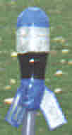
To put them into practice, put a piece of gaffer tape along the side of the rocket and weigh in the optimum amount of water. Mark on the gaffer tape where the water comes to, screw a top on, invert it and make another mark (in such a way that you will not be confused - possibly using an arrow pointing upwards). This will make life easier when in the field and you haven't got access to the scales. If your rockets have tare weights or capacities that are different to these, you can use the above graph to work out roughly the right weight of water optimised for height - this assumes that the rocket capacity and diameter are roughly in proportion. Tests I made 3 rockets for the purposes of testing this out. Two of them already had an almost conical neck (the 250ml and 1 litre) and therfore didn't need modifying there. I modified the 1 litre at the nose end to form a spherical end and, as it was originally a blackcurrant cordial bottle and had concertina style ribs, I blew them out to make a flat(ish) side. As a result, it shrank down to have only 800mls capacity. The 2 litre bottle was treated in accordance with all of this page - spherical end, tapered side, fins, weighted nose - and it shrank down to 1,500mls. All of the rockets were pressure tested to around 1.3 times the normal pressure for twice the normal time of pressurisation. This was done by filling completely with water, attaching the connector described on the 250mls rocket page and pressurising. The reason for filling with water is that water is effectively incompressible and therefore can be taken up to quite high pressures without holding a dangerous amount of energy - the energy in the water rocket pressure tests is from the elastic deformation of the bottle during the test.
These computer predictions worked out to be correct as far as the times and heights were concerned. They were launched from the Copper Tube Launcher, timed and measured.
|
||||||||||||||||||||||||||||||||||||||||||||||||||||||||||||
|
||||||||||||||||||||||||||||||||||||||||||||||||||||||||||||
 bottle, holding the nose (a)
approximately 9" above a gas ring (for those
without gas rings, I have seen a barbecue mentioned as an
alternative although I have not used one myself).
After a while, the plastic will have softened
sufficiently to form a hemispherical shape by itself (b), at
which point, you should cool it down under a cold tap or
in a bowl of cold water.
bottle, holding the nose (a)
approximately 9" above a gas ring (for those
without gas rings, I have seen a barbecue mentioned as an
alternative although I have not used one myself).
After a while, the plastic will have softened
sufficiently to form a hemispherical shape by itself (b), at
which point, you should cool it down under a cold tap or
in a bowl of cold water. Fix the adapter onto the end of
the bottle (a)
as above and put a little less pressure in it this time.
Make sure that the bottle heats up evenly in the area
that you want to reduce by turning it continuously above
the flame in the same manner as a glass blower. If the
bottle is not showing signs of shrinking but is warm
enough then loosen the adapter slightly to let some of
the air out. You may have to do this a number of times
but always have the pump nearby incase you let out too
much.
Fix the adapter onto the end of
the bottle (a)
as above and put a little less pressure in it this time.
Make sure that the bottle heats up evenly in the area
that you want to reduce by turning it continuously above
the flame in the same manner as a glass blower. If the
bottle is not showing signs of shrinking but is warm
enough then loosen the adapter slightly to let some of
the air out. You may have to do this a number of times
but always have the pump nearby incase you let out too
much.
 So where does the COG want to
be? The COG
needs to be between 1 and 2 rocket body diameters (d) forward of the
COD - in
free flight, the COG effectively pulls the rocket
forwards and the COD pulls it back - if they are between
1 and 2 rocket body diameters apart, they are able to
exert enough of a couple (a couple is a pair of equal
and opposite forces that do not share the same axis and
therefore tend to have a twisting effect) to correct
the rocket's attitude during flight.
So where does the COG want to
be? The COG
needs to be between 1 and 2 rocket body diameters (d) forward of the
COD - in
free flight, the COG effectively pulls the rocket
forwards and the COD pulls it back - if they are between
1 and 2 rocket body diameters apart, they are able to
exert enough of a couple (a couple is a pair of equal
and opposite forces that do not share the same axis and
therefore tend to have a twisting effect) to correct
the rocket's attitude during flight. These figures were then fed into
my computer model and the weights in the table below and
graph on the right were calculated to be the optimum for
the pressure range considering the diameters of the
different rockets.
These figures were then fed into
my computer model and the weights in the table below and
graph on the right were calculated to be the optimum for
the pressure range considering the diameters of the
different rockets.