Making Your Own Hinges
Pictures don't normally have hinges but if you want to make a proper diptych or triptych, you will need them.
On the right is a Triptych of the Virgin and Child attributed to Goossen van der Weyden made in the 15th century.
Triptych ('three' and 'folding') means that there are three picture frames, hinged so that the wings fold in, over the central picture. Quite often, the wings also have pictures on both sides so there are in fact five pictures but it is still a triptych.
This triptych is unusual insofar that it has blade hinges so the weight of the wing is taken at the top and the bottom of the wing whereas other hinge types are positioned further away from the corners of the wing. You will see below how this alters the lateral forces on the hinges.
Forces
So, how strong do the hinges have to be? They will be required to hold the weight of the wing as well as being strong enough to sustain the battering that such a work of art will get, being opened and closed over a period of hundreds of years.
On the right, you can see a diagram representing one of the wings of a triptych. The weight of the wing has to be supported by the hinges which will end up as a sheer force, equivalent in each hinge as half of the weight of the wing. But the wing has a width so what other forces are on the hinges?
It is often convenient to represent the mass of a body that is not in rotational motion as a single point as though all of the mass of the body was concentrated there - it doesn't matter if the body is made from gold or balsa wood - it works. It is called the centre of gravity (COG). If there was a large concentration of the mass off to one side or at the bottom or the top the body it would change the position of the COG but in the wing of a triptych, it is fair to assume that it is, as far as makes no odds, in the centre of the object as represented in the diagram.
If we were to suspend a mass that is the same of the wing from two essentially weightless rods that are mounted at the hinge points on the central panel of the triptych, they would appear the same as the two diagonal orange lines in the diagram. At the end where they meet, the weight of the wing pulls them downwards so the lower diagonal line is in compression whereas the upper line is in tension.
The hinges are mounted so that their centres line up and are connected into the vertical surface of the side of the central panel. As the top hinge is pulled, some of the force is trying to pull the hinge vertically along the surface and the rest of the force is trying to pull it horizontally, out of where it is mounted. It is reasoned like this because the surface is vertical and the hinges are secured horizontally into the frame.
You can take the force along a diagonal line like this and split it into two values which in this case will be a vertical component and a horizontal component. representing the sheer force and the pulling-out/pushing-in force. So, how big are these forces?
The vertical force is easy to work out - it is the mass of the wing divided by two.
There is more to working out the horizontal force but due to a nice artefact of vectors, it is a lot simpler than many other things:
The forces can be represented by lines, the length of which are proportional to the magnitude of the force. We know the magnitude of the vertical force and we know the dimensions of the triptych and where the hinges are mounted.
Solving it mathematically
The width of the wing is 1/4 x total width so the COG is 1/8 x width away from the hinges.
The distance of the hinge from the top is 1/7th of the height so the distance from the hinge to the COG is 2.5/3.5 (ie, 1-2/7).
So, if we call:
the ratio of the distance between the hinges to the height of the wing R the mass of the wing M kg The width of the triptych W mm The height of the wing H mm
So, the sideways force on the hinges = W x M x 9.81 Newtons 16 x H x R Examples:
- For a 500mm wide triptych that is 281mm tall with the wings weighing 0.33kg each and the hinges a seventh of the way from the top and bottom, the sideways force would be 1.2N pulling out for the top hinge and pushing in for the bottom hinge. (1.2N is roughly 122g)
- For a 660mm wide triptych that is 371mm tall with the wings weighing 0.62kg each and the hinges across the top and bottom, the sideways force would be 0.7N pulling out for the top hinge and pushing in for the bottom hinge. (0.7N is roughly 69g)
Solving it on paper
Representing the magnitude of the forces using the length of the lines also lends itself to solving it using a pencil and paper.
Simply draw the lines representing the forces with the lengths of the lines representing their magnitude and the angles formed from the scale drawing will automatically represent the vectors so all you have to do is break them down into their vertical and horizontal forces as has been done on the graph paper you can see on the right which uses the forces in the first example above.
It is not as accurate as using the mathematics but it doesn't have to be - adding paint, moving the triptych around and so on will subject it to higher forces any way but it does show you how much force the hinges will have to resist in their normal, static life so you can use materials that can withstand that.
If you haven't got any graph paper, you can print your own using the PostScript files here. There are 1x10mm, 2x10mm and 2x10mm coloured to choose from, printing on to DIN A4 and being PostScript files, you can edit them yourself with a test editor such as NotePad or Kate and change the colours or anything you like. The 2x10mm coloured was the one used in the image on the right.
Click on the links to download:
If you have a PostScript printer, click on the image of the colour bar and you will download a PostScript file called "colourbars.ps" which is a plain text file that you can view by loading it up into your text editing program such as NotePad or Kate and so on. You will see that PostScript is a printer programming language and if you send this file directly to your PostScipt printer, it will print it out as a page of graph paper.
To print directly, you can open up a command line and use the print command like this...
> cd [wherever/you/saved/the/postsctip/file]
> lpr -l [the name of the file you want to print].ps
...and that will send the contents of the postscript file directly to the printer as a set of instructions, as opposed to rendering it as a program listing and printing that out.
So, the force isn't a great one but we need to remember that hinges have to work thousands of times over many centuries without failing.
Types of Hinge
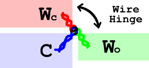
Up until roughly the 14th century, hinges were made from wire which was twisted into a loop that went from the 'core' of the wings to the front edge nearest to the centre panel and on the centre panel - for the reason that there wasn't a picture painted on the back - these loops could be picked up by loops passed through corresponding holes leading to the facing edge from the rear.
These twisted loops are fairly easy to produce, requiring wire to be drawn from whatever the relevant metal was.
Alternatives to metal could be used if required.
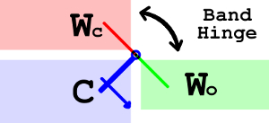
From the end of the 13th century and into the 14th, hinges could be made from bands of metal that were bent into hinges and either nailed to the rails at the top and the bottom or, like here, passed through the corners as in the wire hinges above.
An example of this with original hinges that survive to today is the Wilton Diptych.
These hinges were made from iron and it is this type that we will be making.
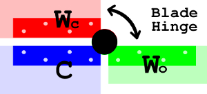
Blade hinges sit at the top and the bottom of the wing, nailed into the rails.
In the Triptych of the Virgin and Child attributed to Goossen van der Weyden made in the 15th century, one side has one blade which sits between two blades attached to the other side, connected with a pin that cannot be removed.
To make these hinges, you need to make three identical blades for each hinge.
Butt hinges are the common or garden hinge that you find holding doors in place in every house.
To make them, you need to produce only two plates the same size, castellate one side of each plate and bend the castellations over to form interlocking knuckles, one of which holds the connecting pin in place.
These appeared in triptychs later on and ever since. They are the hinge of choice for people renovating diptychs and triptychs and so on but not for restoration as they are anachronistic for the early 15th century.
Dates are approximate with practices running into others over hundreds of years.
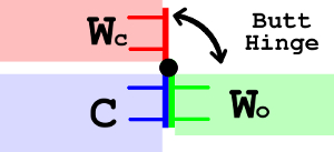
C = Central panel
Wo = Wing - Open
Wc = Wing - ClosedMaking Band Hinges
I dare say that with a forge, anvil and all of the right tools, it is possible to make these just out of forged charcoal iron but that is beyond my resources so, with access to roughly 1mm and 2mm charcoal iron sheets, this is the next best thing. The scale of these objects points towards using a junior hacksaw with 32tpi Eclipse blades and needle files.
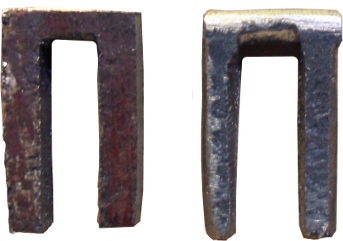
From the 2mm thick plate, I cut this shape which is around 8mm wide and then rounded the top so that it forms one of the sides of the hinge.
Then, I cut a series of notches in the legs so that it can grip the wood of the holes that I drilled for it.
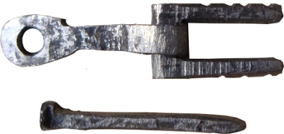
Then, from the 1mm thick plate, I cut a strap, around 2.5mm wide and 3cm long. One end of it, I bent around to form a knuckle that I then wrapped around the other piece.
Next, again from the 1mm plate, I cut a length around 1 to 1.5mm wide and 2cm long from which I fashioned a nail. This, I worked cold with a small hammer, flattening a length to make the head and knocking the other end into a point. I work-hardened the shaft by hitting it cold with the hammer, taking the corners off the square cross-section to make it rounder.
Now, into the centre panel side front edge, I made a hole that the strap could fit in and then drilled a hole small enough to take the securing nail and meet it. I pushed the strap into the hole and pushed the nail in, scratching the surface of the strap, then taking the strap out.
I then drilled a hole (this is done by using a centre punch, hitting it repeatedly and turning it over until the hole falls out) where the scratch was on the strap. Now, I had a strap that I could push into the hole and secure with a nail.
Next, I drilled two holes in the wing front side edge and at the appropriate stage in building the triptych, I hammered it into the wing holes. This is very sturdy, on a test piece, I was unable to pull it out of the oak, even when placing it in a vice and pulling at it with a pair of pliers applying at least 100N (10kg, 22lbs) force. This double-pronged piece certainly can take enough force for at least 10 times the force that it will encounter using it as a triptych. As a framed work of art it will never encounter that magnitude of force. I still haven't managed to get the test hinge out of the wood and I had to make another one to replace it.
With the holes for the nails in the centre panel frame made, the wings can be removed, allowing them to be worked on separately until such times that the process needs them to be secured.
Note that hammering the hinges into the wings needs a fair amount of force whereas knocking the nails into the centre panel needs much less so it is logical to: hammer the hinges into the wings when less work has been done on the artwork and any damage to surfaces is easier to repair; and, hammer the nails into the centre panel as late in the process as it can be done.
Also, note that any holes should be glued as well, to prevent ingress of dust, air, wildlife as well as to add strength in a 'belt and braces' sort of way.
So,
- complete panel/frame woodwork assembly;
- manufacture hinges;
- make holes in frames;
- gesso and sand panels/frames;
- secure hinges in wings;
- paint frames;
- varnish and rottenstone frames;
- secure wing hinges in centre panel frame and hammer in nails; and,
- finish off the artwork.
Here is one such hinge in situ, before gessoing.
All images and original artwork Copyright ©2020 Paul Alan Grosse.
